-
-
-
-
-
-
-
Flaire Group Project
-
-
-
The Flaire
A Chapter582 Group Project
"Building Freedom"
A Chapter582 Group Project
"Building Freedom"
Dear Member:
From this Blog you will be able to learn more about the F-582 Flaire airplane. From design to "projected" performance, you will be able to view, read, comment and even ask questions as production develops.
The airplane is being designed by and built by chapter members just like yourself. So, for those of you who choose, it's ease to get involved... and we'd love to have you! To do so, simply drop Bill David an email (available from the Member Director tab off the home page) or go to the Flaire Forum and add a comment.
If you've never been involved with building an airplane this is your opportunity. For those of you are seasoned veteran to the "building process"... this is your opportunity to give back, by teaching others. We all have something to give and we all have something to gain. We need each other..
And finally, for you arm chair enthusiasts... we need you too. Log-on and follow the progress. Your moral support is the next best thing to actually being there... Join in the Flaire Blog and give us your 2 cents worth.. it won't cost you a dime.
You may even get a response....
Signed:

Bill David Andre Abreu Steve Cechner Ron Sturgill Ryan Weaver
Conceptual Designer Structural Engineer Mechanical Engineer Chief Machinist Psycologist
Chief Pontificator Math Genius Mechanical Genius 1000+ Y.E. rides Chief Speech Writer
 We began design work on the Flaire about three years ago. We wanted to design an airplane specifically for LSA training. Although there are a few airplanes on the market that could be pressed into service, none of them met all of our requirements to the degree we felt was necessary. Here is a list of our top priorities in order:
1. 550 to 600 pound useful load.
2. A minimal airplane for all
four seasons.
3. Simple to build, easy to fabricate parts for.
4. Folding wings.
We live in a world of high fructose corn syrup. There are growth hormones in most of the meat we eat. We are a fast food nation full of couch potatoes, myself included, so the useful loads and cockpits of yesterday don’t work anymore. It seems like everybody is 6’ 5” and 250 pounds. I don’t think I am exaggerating too much, we are big boys and girls now so I figure you have got to have at least 250 pounds for the student, 200 pounds for the instructor, and about 100 pounds for fuel. Baggage is not a factor, see design goal number 2.
If we can lift the student and instructor with enough fuel for cross country training then what kind of an airplane do we put them in? Our answer to that is the least amount of airplane that utilizes conventional flight controls and construction methods. The key word is least. Throughout the design process minimalism was up front and center. By default this makes the airplane cheap and easy to build (priorities) while keeping it simple and light. These are all really good things when it comes to designing airplanes.
Side by side seating is employed to limit the effect on center of gravity changes. It will have adjustable rudder pedals. It also makes it easier to observe the student especially during cross country training. There will be a spring actuated pitch trim. It needs only one set of instruments and a single center mounted control stick. Conventional gear is employed because this is a trainer and tail draggers make better pilots, and for that matter, flight instructors. There will be a Johnson bar for the brakes because not only is the set up lighter and easier to service, it reduces the habit of using toe brake to modulate speed during taxi. It will have heat delivered through a fresh air box that mixes with cold air to control the temperature, flow, and volume. The windows may be opened in flight. It will have conventional flight controls with no flaps. There will be no electrical system, it will be hand propped but will be provided with a set of external mag switches, primer, and throttle control. The wings will fold for storage not trailering.
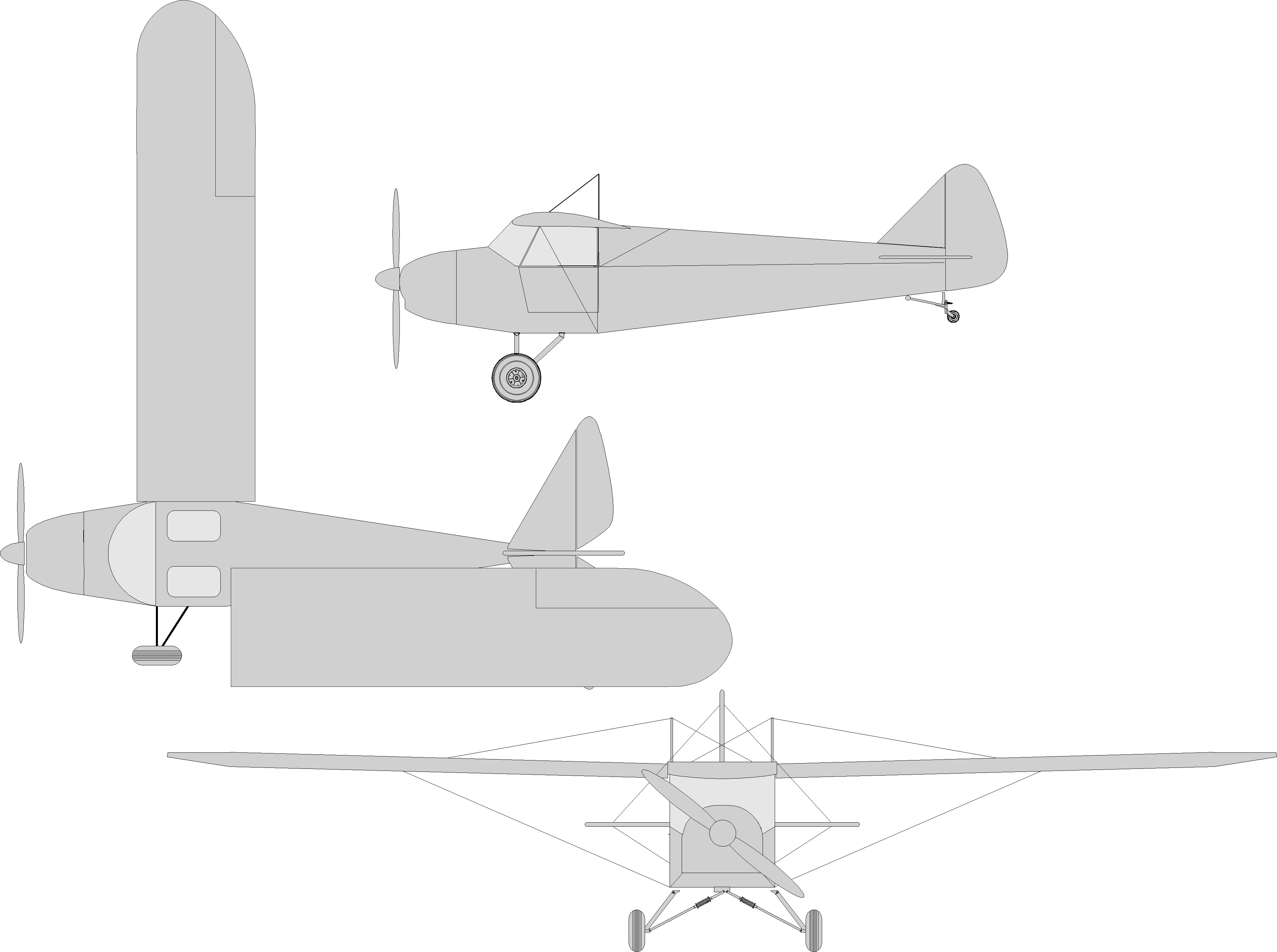
We chose steel tubing because it is so easy to work with. I made sure that there were no bends in any of the tubing except for the control surfaces. These are quite easily bent when filled with sand over a simple forming block. The empennage is conventional steel tube and ribs. The main landing gear has coil springs for shock, six inch wheels with differential braking. The tailwheel is a full swiveling, manual locking, coil spring shock, design of our own.
The wing is all aluminum with foam nose ribs wrapped in aluminum. There are no compression ribs or drag wires in the wing. It has cables for flying and landing loads, and the wing swings aft to the folded position. A single lever will lock and unlock the spar attach pins and the ailerons automatically connect and disconnect when the wing is swung into position. The entire airplane is covered with fabric.
So there you have a brief overall description of the airplane. Keep in mind the sole purpose for this airplane is for flight instruction in the LSA category. Aesthetics were not considered, function set the form. Only the flight control surfaces have a “look,” to them which is decidedly retro, and that is because it was easy to do. It has a Continental 65 hp engine because they are cheap and bullet proof. The “environmentals,” where designed to provide maximum comfort, not just super hot air blowing on one foot. The windows open in flight in order to get that open cockpit feeling for summer, while still allowing the cabin to be sealed for flight in rain and cold winter air. Serviceability is considered to be important to allow for maintenance and accessibility. We are considering a swing out engine mount.
We did ourselves a favor and rather than redesigning the wheel we basically copied the measurements of the Aeronca C-3 Collegian. It was a low cost airplane that was very successful. You could call our rendition a C-3 personified. It is not a fast airplane, it is not an attractive one either. However it will provide us with a very low cost, very cheap to operate, dependable, all season trainer. Hopefully this approach will deliver an airplane the meets our design goals so that we can start teaching people how to fly in it, one LSA pilot at a time. M boy.
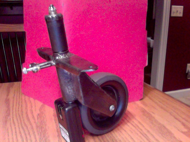
I just finished welding up the tail wheel this afternoon, 01-03-2014. It weighs less than three pounds so far. It will probably end up being a little less than four pounds when I'm done with it. It is loosely based on a Pietenpol Aircamper only with some improvements. We have had a few years of experience improving the one we have on our Piet. We experienced many failures but I think we finally have it figured out. The wheel can be found for about $5.00 at just about any home improvement store. The rest of the materials are probably another $10.00. It has a simple manual spring pin locking system that will be controlled from the cockpit. Simple, light, cheap, and effective. That's what I'm talking about.
Now that I have the gear legs welded up I am able to attach them quite easily to the floor section. Having welded up the floor made it much easier to perform the fitting process. Everything worked out well and it only took a few minutes to tac weld it up .. The only problem I ran into was not having enough material to make the gear leg diagonals fit to the designed attach area, they had to be cut too short. The front attaches as planned but, the diagonal is a few inches forward of were it should be. I figured this is OK and I will include an additional stiffener were it sets now but, it probably isn’t necessary. A good structural engineer could provide analysis to prove this.
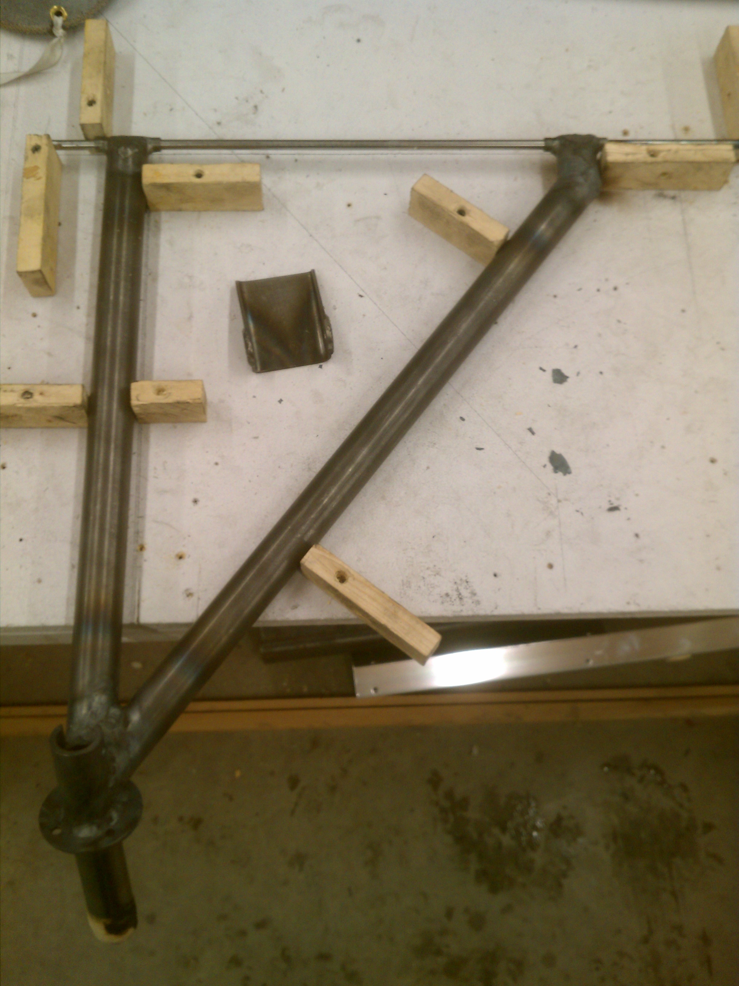
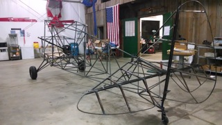
Other than that it is all good. The main and tail landing gear are completed and now we can move on to welding the fuselage structure together.
So we didn’t quite get her up on her gear on MLK weekend but we had a heck of a lot of fun trying. I already had the floor tubes welded together and had the landing gear attached to it as well. It was pretty easy setting the gear up. What I did was attach the legs to their respective brackets and then
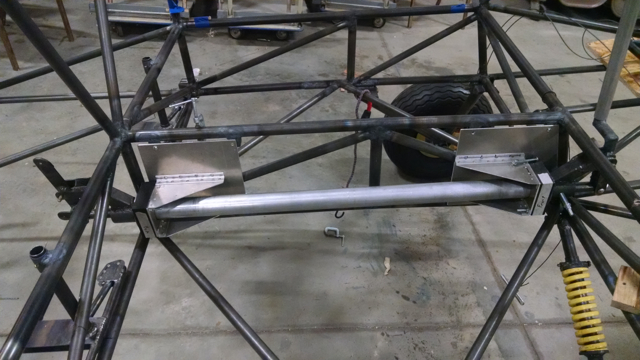
set them on the floor tubes upside down on the bench. Then I stuck a long tube through both of the axles so that they were in as good alignment as possible. Then I measured and turned the axle spring tubes to a length that would allow a little bit of positive camber, http://tinyurl.com/q9kn82k. This was totally a guess but I just wanted a little bit so that the wheels would meet the grass square when the weight is on the wheels. If I am off by much I have designed the attachment to be shortened.
I fabricated a center attach fitting out of 1/8” steel to the floor structure to accept the upper end of the spring cartridge. This will be welded to the center section of the floor an should be strong enough to take the loads but it is another of many guesses.
Once I had all this stuff pinned together and set just right I tack welded it in place with the MIG and then finished
welding them with the torch.
I forgot to say that I also completed the top fuselage spline and the firewall tubes the week before. I think I was done with them on Friday. Anyway the spline consists of the upper cabin and wing attach structure and it has a central spline that forms the top of the razor back. This is where I made my first mistake. I pre mounted and drilled the vertical and horizontal stabilizer attach points and welded them into position. The front of them is attached with an AN 3 bolt that runs through a bushing which is welded into the 7/8”x.049 spline tube. The aft portion of the vertical simpley sleeves into the tail post and I fashioned a bracket with a 3/4” tube that sleeves into the aft horizontal stab tube.
My thinking was that I could do a real nice job of drilling and welding while I had it on the bench. That didn’t work out so good as you will see.
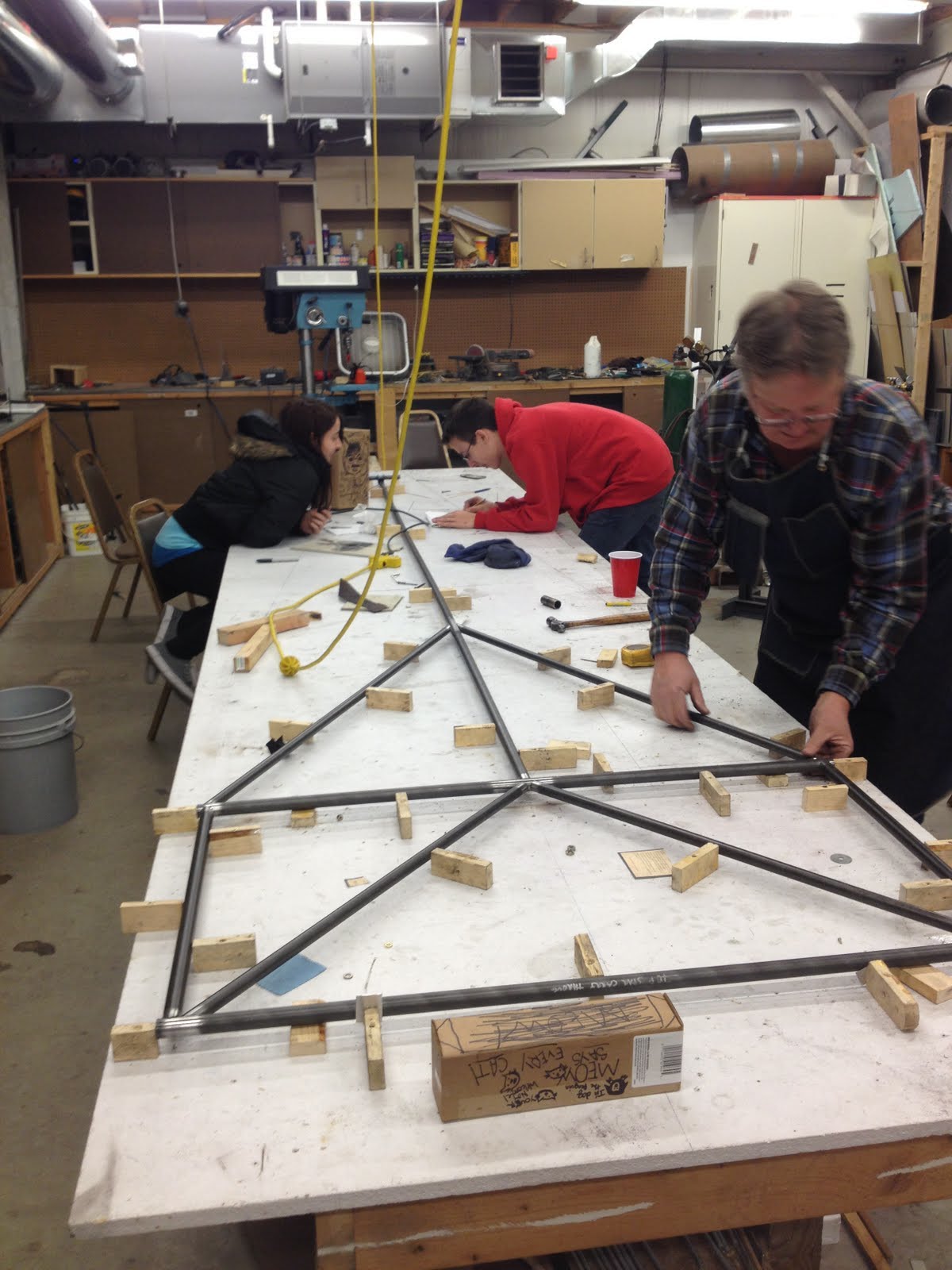
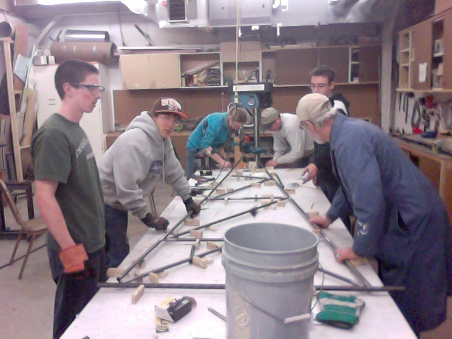
So on Saturday morning we started to assemble the rest of the fuselage. I designed it so there are no bends, all straight tubes with simple fish mouth type joints. We started by laying out the bottom forward section of the floor. Everyone contributed to the layout and construction. I went over the basics and demonstrated on a few tubes. By the time we were done with that everyone had a general idea of the process of cutting and welding steel tubes. I did all of the welding and they started measuring and cutting. It wasn’t until the next day that we figured out we laid the forward floor out wrong. It didn’t fit to the firewall tubes. Oh well, I ended up making a new firewall.
The next step was the aft fuselage bottom. It is a simple truss with cross members in it. We were able to cut out and weld that structure up by the end of the day. It all looked great and everybody went home with a sense of accomplishment.
We were back at it bright and early on Sunday morning, We jigged up the from and back bottom structures to the middle floor section and welded them together. Next we tack welded in the aft door verticals. They are designed to be set at 90 degrees to the middle floor board. Once they were cut and welded they provided the support for the upper fuselage spline. This is where we started to go wrong again. Although we were very carful to make sure that the cabin structure was square before we welded it, we neglected to make sure the it was square longitudinally. Unfortunately I didn’t notice this until the next day. I had to spend about an hour straightening it out using a torch and a bar clamp.
Now that we had the upper and lower structure welded in place and welded to the tail post it was a simple matter to work from the front toward the back installing the diagonals. This partially completed structure acted as a jig to set them in their places. By the end of Sunday night we were only about half way finished with the diagonals. Like I said, we came close but we didn’t get her on her gear. What did happen though was that our crew now had some experience with building a steel tube fuselage.
The next week I came out and worked by myself. I finished up some of the diagonals in the forward cabin area. About 90% of the tube work is done and we should have it all done this weekend. Then we will begin to fabricate and install the flight controls. Another member, Joe Deaton is heading up what I call the ergonomics. This would be the design and installation of the seats and other interior components. He will also design the instrument panel and locate the controls for fresh air and heat.
Looking back on what we did I would make these observations. First, don’t pre-install the vertical and horizontal attach points. The fuselage distorts enough during welding that their alignment changes. In the coarse of straightening out the cabin area, I had to use a bar clamps and heat to get it right, the position of these attach points changed so I had to make new ones. Of course you want to make sure that everything is lined up in the first place in the cabin area before you weld it. Another thing is that since the cabin wasn’t straight in the first place the rest of the spline fell out of alignment as well. I was able to fix all of these problems but there will be a wavy appearance to the spline. Oh well, I think it adds character.
We don’t have to worry about the angles of incidence on the vertical or horizontal stabs because I made it adjustable. That way we can pick an angle and if it doesn’t work out it is just a simple matter to change them, in just a matter of minutes. The wing attach points are pretty much written in stone but they can be adjusted to some degree before final assembly.
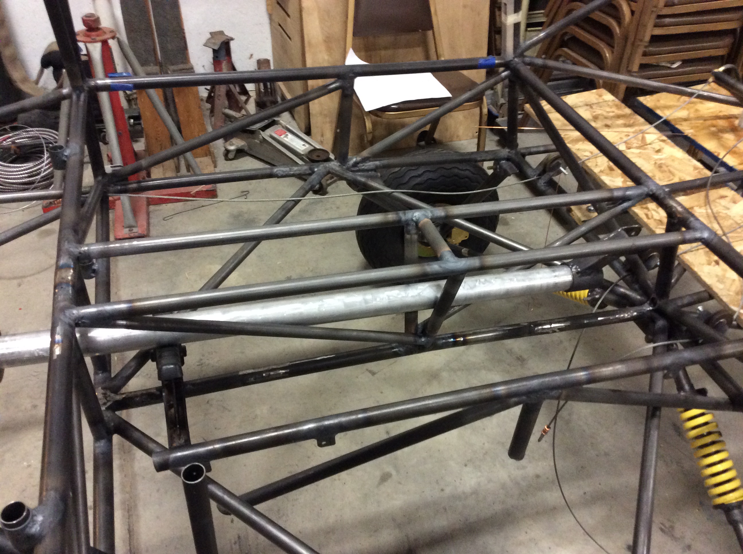
We stuck the whole thing, wheels and all on a set of digital scales. There were still a few more tubes to weld in when we did this but it weighed in at 157 pounds. Andy said that was within two pounds of what his computer drawing said it would be. Add another 100 pounds for controls and instruments, another 200 for an engine, prop, and cowling and you come up with about 460 pounds. If the wings end up being 100 pounds each we are in the ballpark of a J-3 Cub. We shall see.
Another thought is that I may have made it just a tad too big. Sitting in the cabin at this stage gives the impression of lots of room. I expect that will change once all of the stuff in installed. If it performs halfway decent with 65hp it should do better if we make the next one a bit smaller but who knows, it may be just fine the way it is. Another thing to think about is making mistakes. Although we have done most of the construction very well, we did make some mistakes. You will make some mistakes. Somewhere in our society we have learned that it is bad to make mistakes and most of us go through life without admitting to the mistakes we make. People will look down on you if you do. I can tell you that people that think others or beneath them because they make mistakes have never done anything worth while. That is a fact. If you build an airplane, even if it is a kit, you will make mistakes. Someone told me once that there is no such thing as a mistake, it is more like an opportunity for a solution. I agree and it is fun coming up with solutions to our mistakes but, in the long run it would be nice to do without them. I guess I can dream can’t I?
It has been quite some time since I have updated this blog. As I am typing this it is freezing cold out side and we have just received the first snow of the year. The flying season is over and the building season is underway. I think I have already mentioned that I am not the greatest at this internet stuff but I will try to improve the site with more text and pics. I may even try to make a video to post here that will give you all a pretty good idea of how much progress has been made lately.It has been quite some time since I have updated this blog. As I am typing this it is freezing cold out side and we have just received the first snow of the year. The flying season is over and the building season is underway. I think I have already mentioned that I am not the greatest at this internet stuff but I will try to improve the site with more text and pics. I may even try to make a video to post here that will give you all a pretty good idea of how much progress has been made lately.
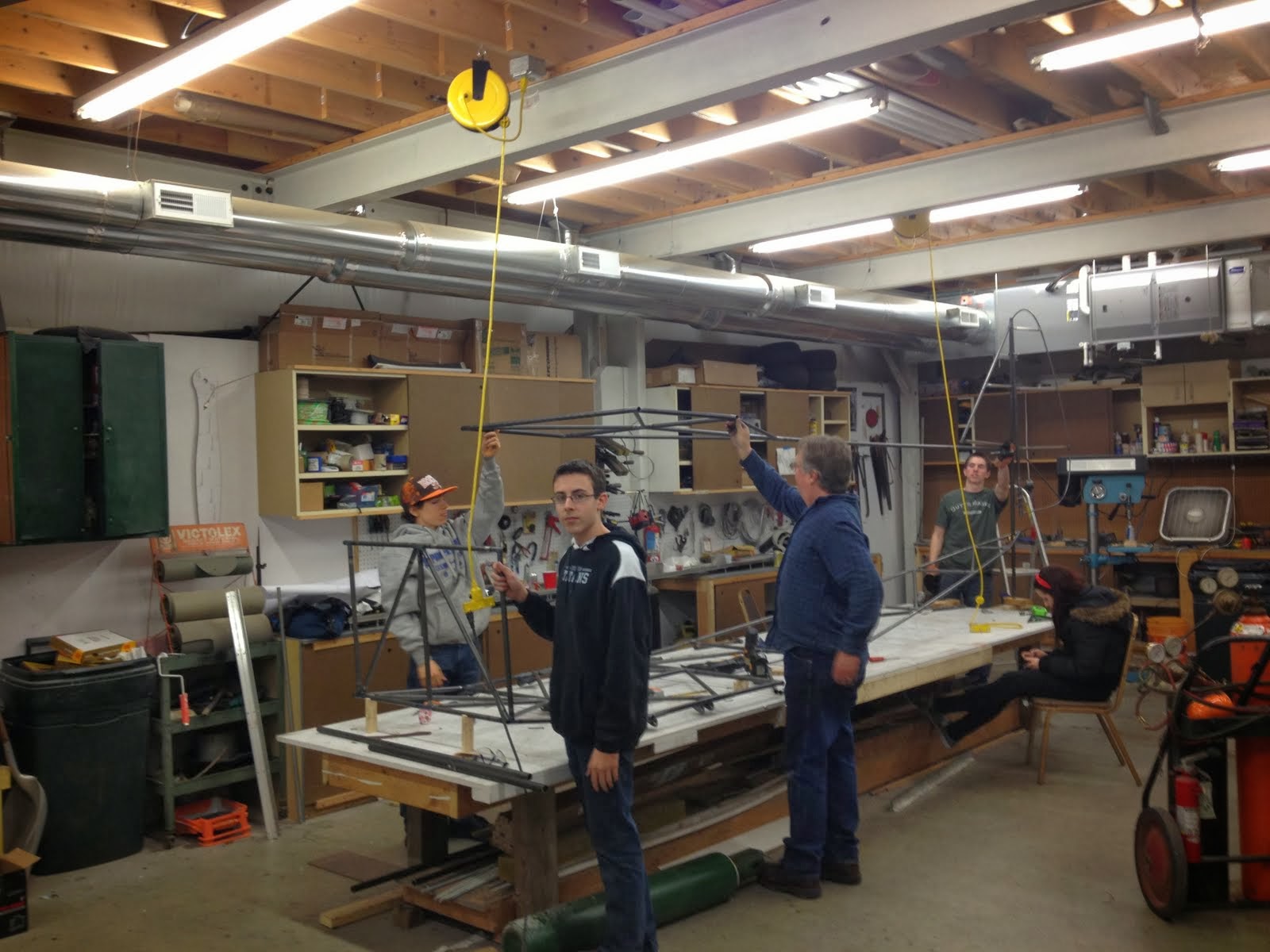
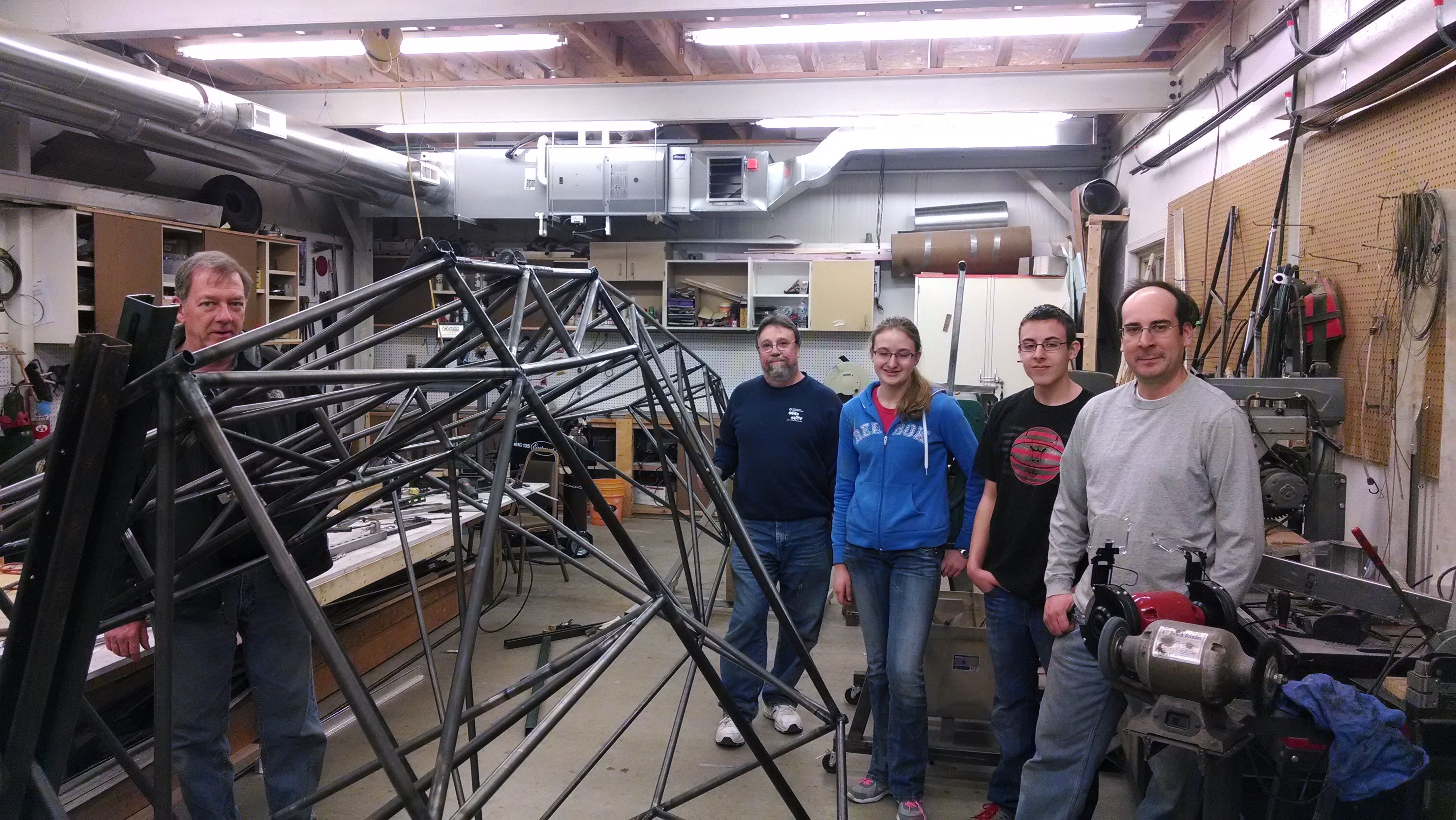
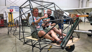
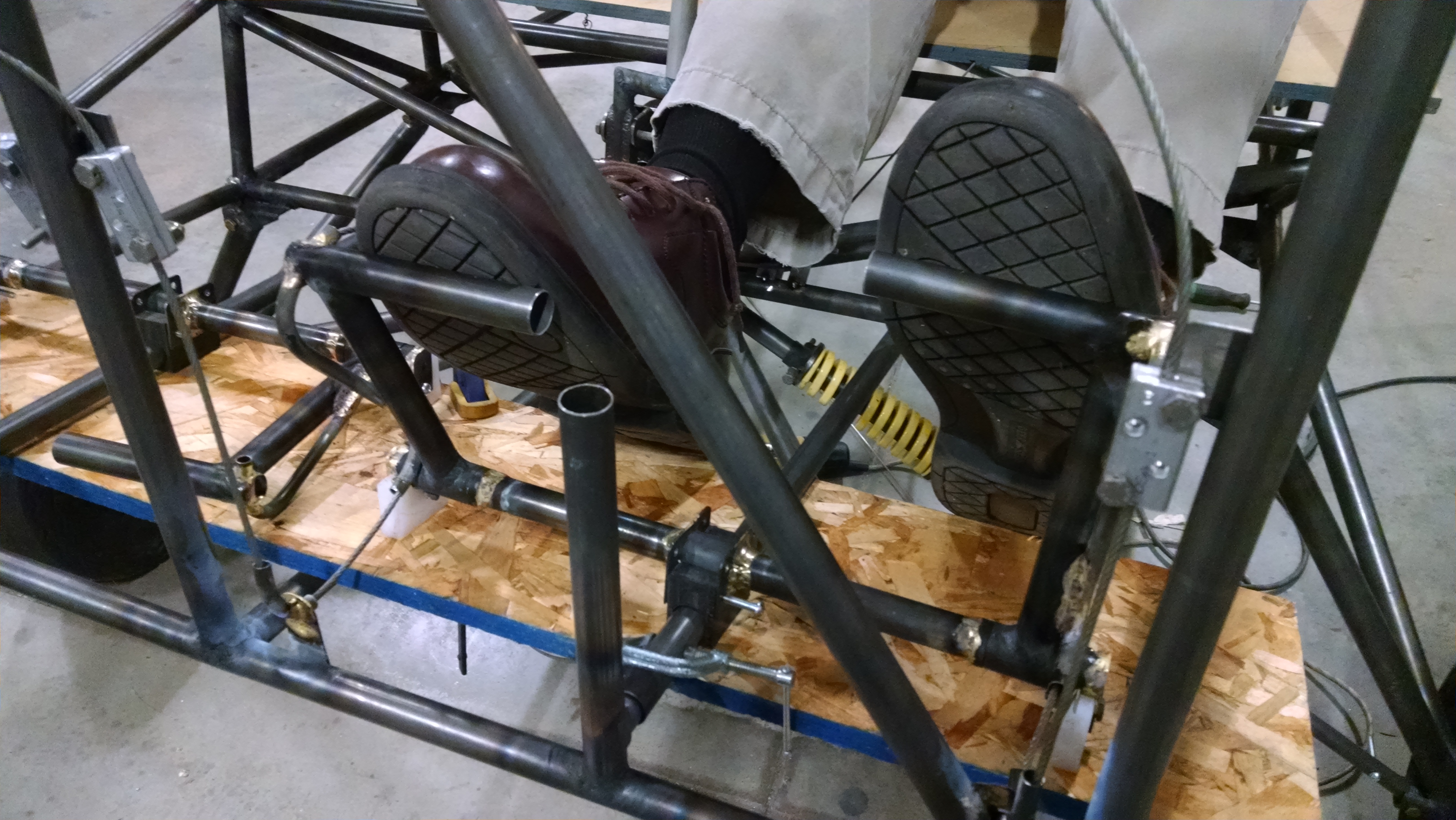
I can report that things are actually going pretty good on all fronts. My plan was to make the basic fuselage and get it up on the gear. We actually got that done a few month ago and here is a picture of my first grandson, Billy Gibson and his father Brian trying it on for size.
The next step was to put the controls in so I started out with the control stick. As soon as I got started I found something I overlooked in the initial design. The truss in the center of the cabin meant that the control stick had to mounted off to the side. It is hard to see how I could have missed this if you have never attempted to design and build something as complicated as an airplane. If you have, you understand. It really was not much of a problem, all I had to do was mount it on the side of the truss and offset the stick a little bit to get t back in the center. On the next one I will address this situation and have already changed the design to a triangular tunnel to run the torque tube through. Here are a few pics of the pitch and roll control assembly. I cut out a couple of bearing blocks out of plastic and us metal washers for thrust bearings. Simple, easy, and cheap while being fairly light weight.
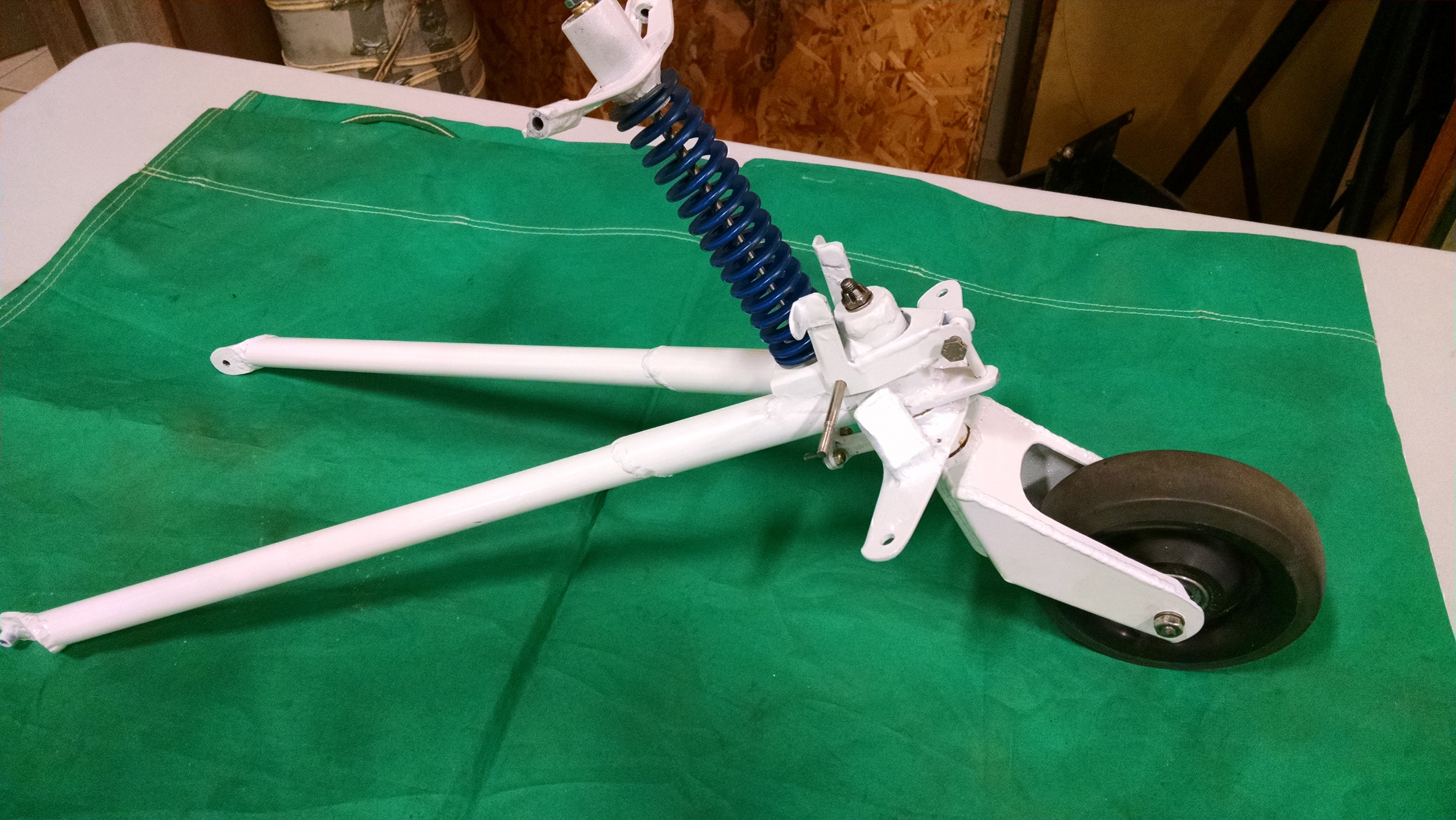
Check out this sweet tail wheel I made. Like I said before it is loosely based on a Pietenpol Aircamper tail wheel but I beefed it up quite a bit and added a few features to it. The first thing I did was make it a manually operated locking full swivel. There is a spring loaded pin that snaps in place and allows the pilot to steer the airplane with spring steering. If you have to make a tight, or locked wheel turn you pull a lever in the cockpit that retracts the pin from a slot in the spindle allowing the tail wheel to unlock and swivel 360 degrees. This will be used mostly for maneuvering the airplane in the hangar. Since this airplane will be hand propped to start it I added another feature to enhance safety. Before starting, the airplane may be secured by tying the it down first. Once it is running the pilot will strap in and pull the same lever that unlocks the tail wheel. A cable will lead to a release on the back of the tail wheel and the airplane can then taxi free. It has a die spring for a shock, stops to limit the travel when pushed backwards, and an oilite thrust bearing in the top of the housing where the spindle rests. It weighs in at 5 pounds, 1.7 ounces in this picture and I bet we have less than $25.00 in it wheel and all. This is the first part of the airplane to be completely assembled and ready for flight.
My goodness, was it ever a struggle to get the adjustable rudder pedals installed correctly! I just got home after putting another full 8 hours of work on them. First off, I really didn't know how they were supposed to work. I knew that it was possible to make them because a long time ago I saw a drawing for a set to go in a glider that Richard Schreder had designed years ago. Richard was a genius. Google him and read up on his series of homebuilt gliders he designed. I was lucky enough to get to know him just a bit. I picked up a couple of Piper Aerostars from the factory out in California and delivered them to his FBO in Bryan, Ohio. He taught me how to bend aluminum leading edges for an ultralight I was building. One time he was grading papers from graduate students majoring in aerodynamics, I think they were from M.I.T, and he critiqued them for me. He was not happy what any of them had submitted, but I am digressing.
So I had an idea of what needed to be done, a simple “S’” tube snakes through the rudder pedal and then gets fixed to the firewall. If you saw a drawing and thought about it for a while you would see how it works. This allows the pedals to be moved fore and aft along the cable and when locked in a fixed position they will act just like any other rudder pedal. You just have to fashion some kind of way to move them and then lock them in place. It gets a bit more complicated if you want to have two sets of independently adjustable pedals and it also makes a difference if you sit tandem or side by side.
The rudder post then slides along a tube in the center. I had originally designed to to have two tubes. Searching the internet for pictures of adjustable rudder pedals and finding quite a few actually, couple with the fact that I had already begun to discover problems of interference with my design, I used what parts I had already fashioned and converted it over to a single center slide tube. What I am proud of is it will take the removal of only one bolt to remove the entire assembly and it will fit on the other side or even go into another Flaire.
In order to make it removable I had to fashion a set of cable clamps to tie the cable fast to the firewall. It took me a whole day to come up with one that would actually work but it is really sweet. Now you can loosen the clamp and slide the cable backwards through the S tubes to remove the rudder pedal assembly. This not only binds the cable but it also allows you to adjust the pedal position perfectly without any expensive turnbuckles.
Since I chose the side by side seating arrangement both sets had to be ganged together to synchronies them. This was fairly easy to figure out and I made a sketch of the concept some time ago. I thought I had it all figured out but I was not really sure if it would work. I had made all the parts, a couple of bell cranks and a push rod. I took number of ttys before I was able to bend the S tubes. I used 5/16” brake line tubing from the local auto store, crimped the end, filled it with sand, tamped it down good and tight, then crimped the other end closed. Then I used a small brake tube bend to make the S curves. This turned out pretty good after some practice. I brazed them onto the rudder pedals.
So I had all the components made and all I had to do was install them, tuts when I started to have problems, interference problems. I wanted to keep all the cables running as close to the floor tubes as possible in order to leave room for some big chunks of styrofoam to put under the seats. The purpose of the foam is to help protect your spine in the case of a very hard crash landing. I know a couple of pilots that hurt their back this way so I think this could help in the event that a fellow pancakes it in pretty hard.
Trying to set the pulleys to make this happen fused be a fit. I worked to whole days trying to make this work and in the process of it Steve walks up and tells me that the geometry is not right on the cables and for and aft movement and that when moving them I will make the cable tighter, or looser depending on the way they are moved. It took me a while to figure out what was so clear to him and I finally got it. Damn, not my little plan was not going to work, I thought I might have to go back to the drawing board but, I pressed on as planned. To my surprise the geometry had a positive effect on the pedals when you moved them If I move them toward the back like you would for a shorter person the pedals actually start leaning toward the back. This means that you don't have to actually move them as far to get them closer to you. I got lucky
So today is the third day of working all day on the pedals and they work slicker than cat gut on a brass door knob. Heres the thing, who you going to ask about how to design a set of adjustable rudder pedals? I know there are a few people out there, a very few for sure, but I don’t know anybody, until now. Getting everything to line up right took some time but I got it. It will be easy to duplicate the process on the next airplane.
03Dec2014
By: Andy Abreu
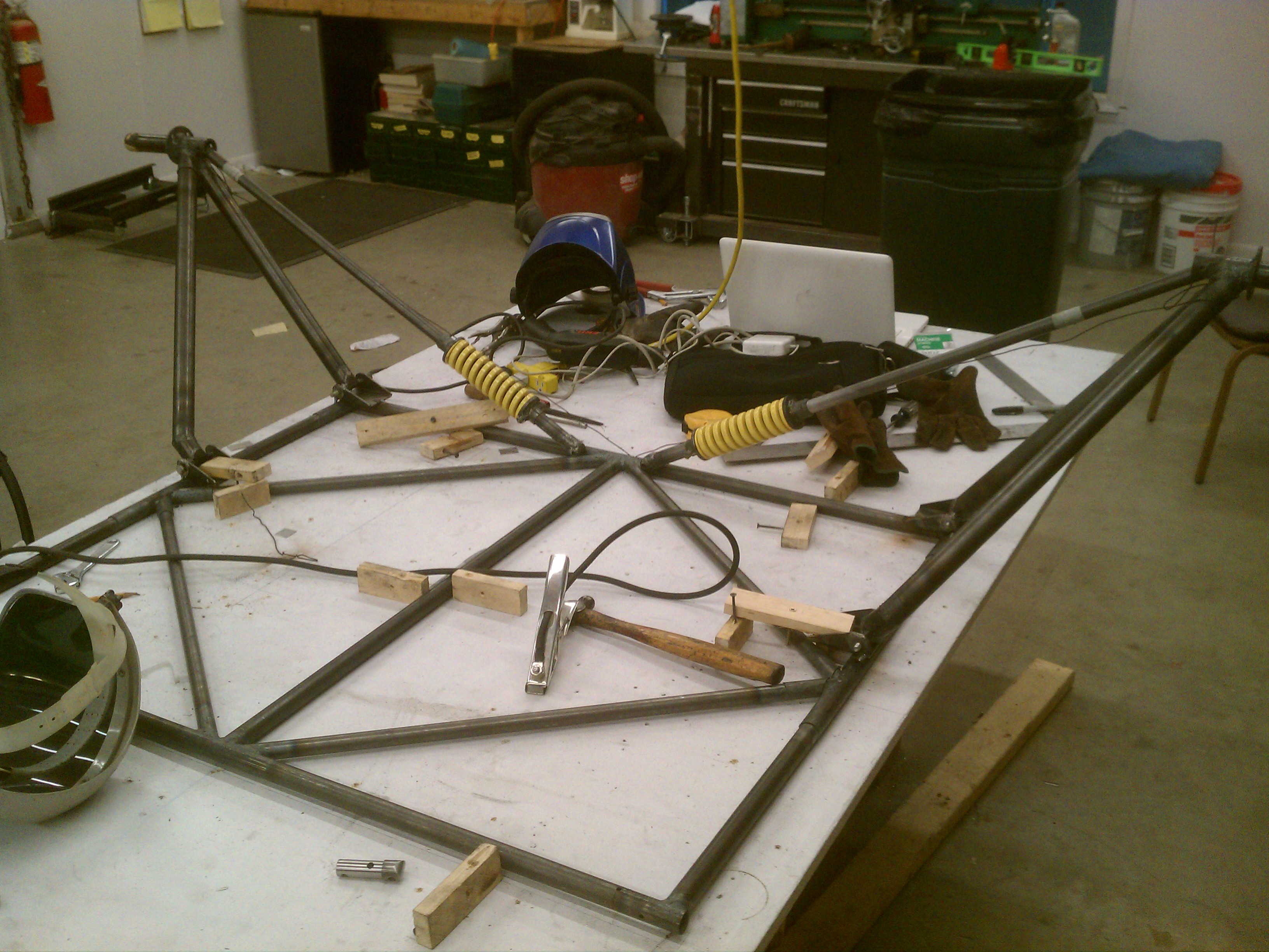
For those out there following the progress of the Flaire "F-582" project, you should be aware that the fuselage has been coming together over the past 12 months. The controls are in for the pitch and yaw systems. Another area of construction is starting soon -- the Wings. The design is unique in some ways. While many newer airplanes have a fully stressed aluminum skin and spar that take all the flight loads, we opted for an open frame design without drag and anti-drag wires. The idea to eliminate the wires is unusual and it means that the internal structure needs to handle all the loads. The structure is similar to a truss with some members needing to take loads in compression, tension, bending, etc. The picture below shows all the members of the wing. The ribs are arranged in a zig-zag pattern to take up the load normally handled by bracing wires. Wires are extremely strong in tension and light. This is hands down the best way to carry these loads. However, turnbuckles are needed and they cost an arm and a leg. Eliminating these is one of the main efforts of this design.

The main spar takes most of the loads in bending, and was probably the easiest part of the wing to size. However, making sure the structure could handle the compressive loads was a major concern. Unlike in other airplanes that have very stuff and very straight members to handle any compressive loads, we were asking the not so straight and not so stiff ribs to do the job. I had my doubts. So I built two wing sections, and with access to a load tester at my work, I was able to crush them to failure. From this test, I estimated that each diagonal leg would be able to handle a compressive force of 600-800lbs before catastrophically failing. My original hand calculations estimated that the structure would need to hold a compressive loads up to 1300lbs.

The previous hand calculation was way too conservative. When an FEA was performed assuming a more uniform distribution of the loads, it showed that the ribs would experience a load around 500-600lbs compressive force in the worst case. The previously tested truss section survived a slightly higher load! This is a good thing and shows that the wing design has a chance of working.
Armed with this new information, we are going to push forward with this design.
- The next step will be to design an attach fitting for the flying wire.
- Design and build the remaining fixtures and templates.
- Build a full sized wing including the D-section.
- And Finally: Test the wing by loading the wing structure with sandbags at a critical angle of attack until failure. The wing will need to carry a minimum load to achieve the 3.8G with 1.5X safety factor. The load will be distributed to mimic the actual load distribution along the span-- reaching up to 14lbs/inch in some areas. The load outboard of the flying wire reduces to zero as it reaches the tip.

We’ll see you out there.
May 5, 2015
Ok, here is my long overdue update on the Flaire. It is now April 26, 215 as I write this and I have been doing quite a bit of work on the project but, I have made little headway toward completion. The fact is that I have been making a lot of changes to systems I have already installed. When you design an airplane or any other thing for that matter, you can only visualize so much. It is true that if you use a 3-D drawing program you can take the process forward to a much more precise degree but, you can't figure it all out perfectly in advance.
This is very true of the adjustable rudder pedal system. Where can you go to talk about such a system? You sure as heck can't go to Home Depot and ask an associate. No sir boys and girls, you gotta figure it out on your own. Of course the internet is the source for all answers in the universe. I found a few photos that gave me an idea about what needs to be done to make them work. So I built a set that have the traditional "S" tube in them to route the cable past the pedal in a fashion that will allow them to slip along the cable to and fro while providing a rigid enough fixture to allow the pedals to "grip" the cable once they are set in the desired position.
This is not what I had envisioned in my original design. What I had in mind was a set of small pulleys located at optimal positions on the side of the pedal. But, I built them in the way everybody else does, at least that I could find pictures of on the internet. I figured why reinvent the wheel? Without going into too much detail, after I put the S tube into motion they presented a number of problems. First off, they were difficult to make. Oh sure I could make them, all day long especially if I built some custom rollers. Second, you can't weld them to the pedal, you have to braze them. I had never brazed before and it is not hard to do but there is a learning curve. The biggest problem or issue I encountered with the S tubes was that they did not flex with the cable at the entry and exit ports on the S tube so the cable, which would be stationary in a pedal locked position, would experience sharp bending loads when the rudder was worked. The same was true on the guide tube that directed the cable up along the firewall. And finally cables needed to be clamped in their fixed position with no fitting on them because you couldn't fish the cable through the small diameter S tubes, which by the way had to be lined with nylon tubing to reduce cable chafing at the ingress and egress points. I brazed the ends of these cables and then ground them to a minor taper so they would snake through the S tube in order to make it easy to remove the rudder peal assembly. I insist on this concept of ease of serviceability.
In a nutshell, I wasn't happy with them so I tossed them aside an built another pair like I had envisioned in the first place. It was a couple of days effort of back tracking but they work slicker than cat gut on a brass doorknob! Oh sure the cheap little pulleys work great but they are too heavy. They should be replaced with a set of nylon ones that we can turn out on the lathe. The aluminum side guides make it impossible for the cable to jump the pulleys. I could put a couple of nico thimbles on the end now and nail them directly to the front firewall tubing but I'm going to press on and use the clamps I made for the first set.
So I'm happy with the rudder pedal assemblies which by the way are interchangeable and are held in by only one bolt. Serviceability dude, serviceability. Now for the hand operated differential brake system. I couldn't find any information on these at all on the internet. Toe brakes are a bad idea for students to learn on. I know that is how we do it in this country but it is a really bad idea. I find that a lot of pilots use their toe brakes to control the speed while they are taxing. I have seen several tail draggers flip over on landing because the pilot landed with his/her feet on the brakes and I have seen them stand them on their n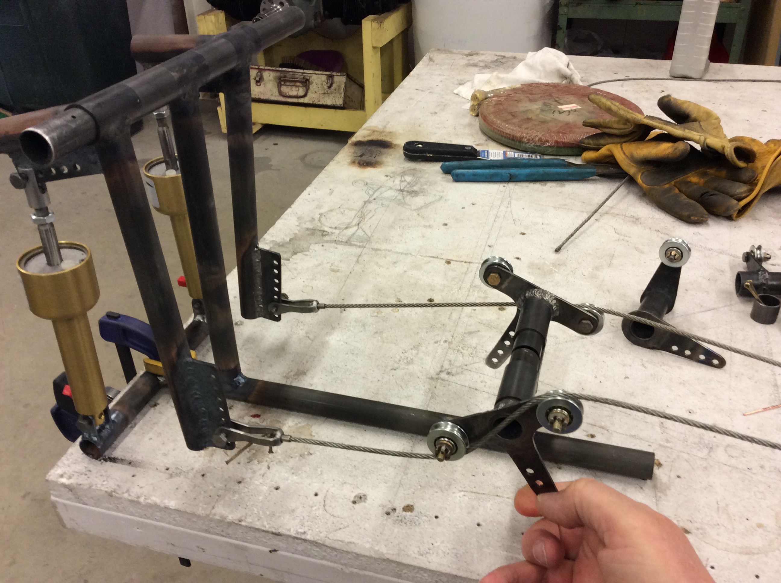 ose too, while they stopped quickly on pavement. When you do this in a nose dragger it covers up for your mistake allowing you to continue poor technique. So we are going to use a hand brake system.
The Dehaviland Chipmunk has a great hand differential hand braking system that can be over ridden by the instructor if necessary. The question is how did they do that? Like I said I tried to find some information but couldn't. A friend of mine has one and neither he or his mechanic could explain to me how it works. He said I could take it apart and figure it out but if you ever worked on an English automobile you can imagine what and English airplane would be like. I passed on this and set to trying to figure it out for my own self.
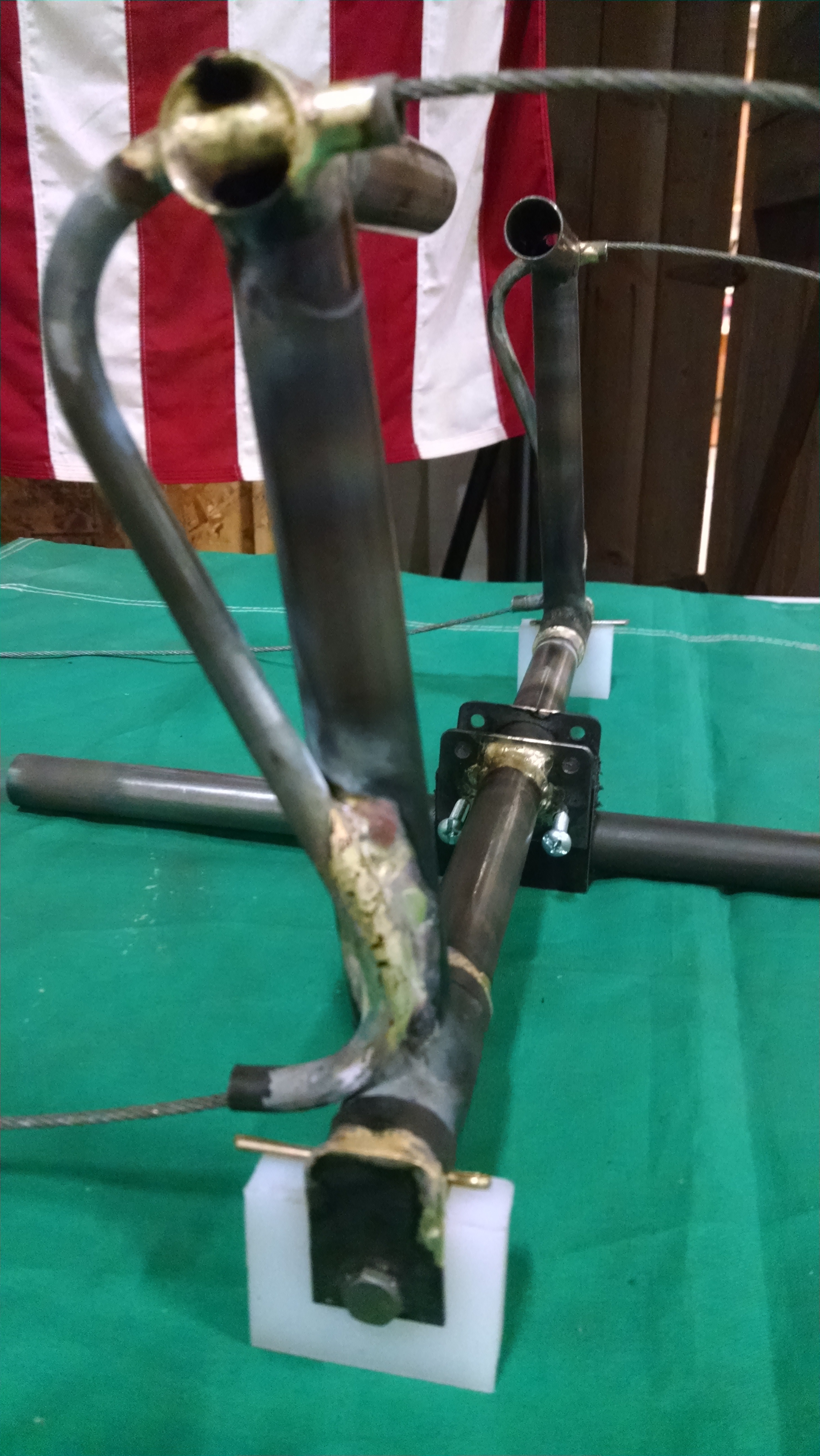
What I came up with took several ties but I think I have it nailed down, we shall see. The simple explanation on how it works is that there will be two brake handles on a torque tube under the seats. There is one handle for the left and one handle for the right seat. Somewhere on this tube will be located a horn or perhaps two of them, that will lead back to the brake cylinders located behind the pilots in the back of the fuselage. So when you pull on the handle it applies pressure to both of the master cylinders evenly. The second part of the equation is a separate cable that leads to the left and right side of one of the rudder synchronizer bell-cranks. You need to have these bell cranks in order to have both the pedals move like the do in all side by side airplanes that have two sets of rudder pedals. It is just a little more complicated if you want to have adjustable pedals.
So what these cables from the bell crank do is shorten the respective cable by however much the rudder is displaced and on the side of the rudder displacement. This happens while the other cable stays the same length therefore holding the same amount of braking as demanded by however hard the handle is pulled back. Got that? If you pull on the handle a little you will get a little braking on both sides but, if you push a pedal while holding that pressure the cable on that pedal is effectively shortened. Walla! Differential hand braking, I think, we shall see.
This system is a little heavier than the simple set in most airplanes, however, they usually don't have adjustable rudder pedals. I know that I can lighten it up a bit by using aluminum bell cranks and horns. A couple of other points are that the assembly will be held in by only one bolt and it will be interchangeable with other aircraft. I built, discarded and rebuilt this assembly four times before I was happy with it. It took me a spell to get it right but I recon it will work I guess.
 I changed t
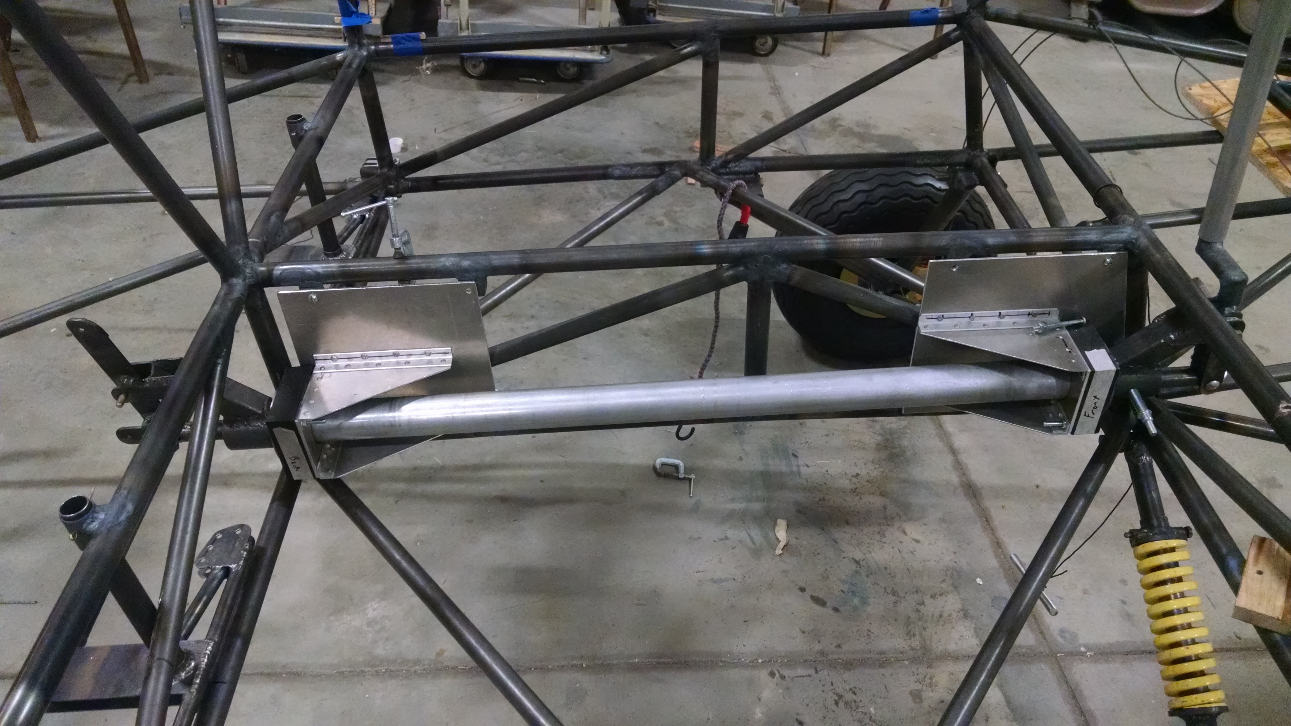 he position of the control stick too. I originally had the aileron and elevator controls attached to the right side of the center seat support. This caused two things that I eventually couldn't live with. First, the stick was offset to the right by about 3 inches or so from center, which was no big deal. The other thing that was a condition of this simple installation was the stick was probably too far forward. Although it might have been OK, I just couldn't live with it. Simplicity had to give way to function. I ended up cutting the center truss that runs between the two seat almost completely out. The only part I saved was thee center bottom tube. Then I had to use two tubes to allow the center mounted control stick to come up between them. It took a few more tubes than the original idea but it allowed me to mount the stick exactly where I wanted too. I think I moved it back about 6 or 8 inches which removed a small amount of weight. Now the whole system is mounted right in the center like it should be. It's more gooder for sure.

A friend of mine has an industrial sewing machine.jpg) and was kind enough to make a seat for me. Too bad I'm gonna throw it out too. When I changed the control system it made the cabin a little narrower and now the seat won't fit. It also needed to have one more piece of strapping sewn into it. I have also changed the way tension is put on the seat pan that costs less, weighs less, and is more effective. Again more gooder. What we have is sort of a sling seat that is made out of nylon reinforcing straps and parachute pack material.. I like these seats because they a cheap, easy to make, and most of all they only weigh a few pounds each. Steve Wittman would be proud.
and was kind enough to make a seat for me. Too bad I'm gonna throw it out too. When I changed the control system it made the cabin a little narrower and now the seat won't fit. It also needed to have one more piece of strapping sewn into it. I have also changed the way tension is put on the seat pan that costs less, weighs less, and is more effective. Again more gooder. What we have is sort of a sling seat that is made out of nylon reinforcing straps and parachute pack material.. I like these seats because they a cheap, easy to make, and most of all they only weigh a few pounds each. Steve Wittman would be proud.
I also changed the position of the rudder bell cranks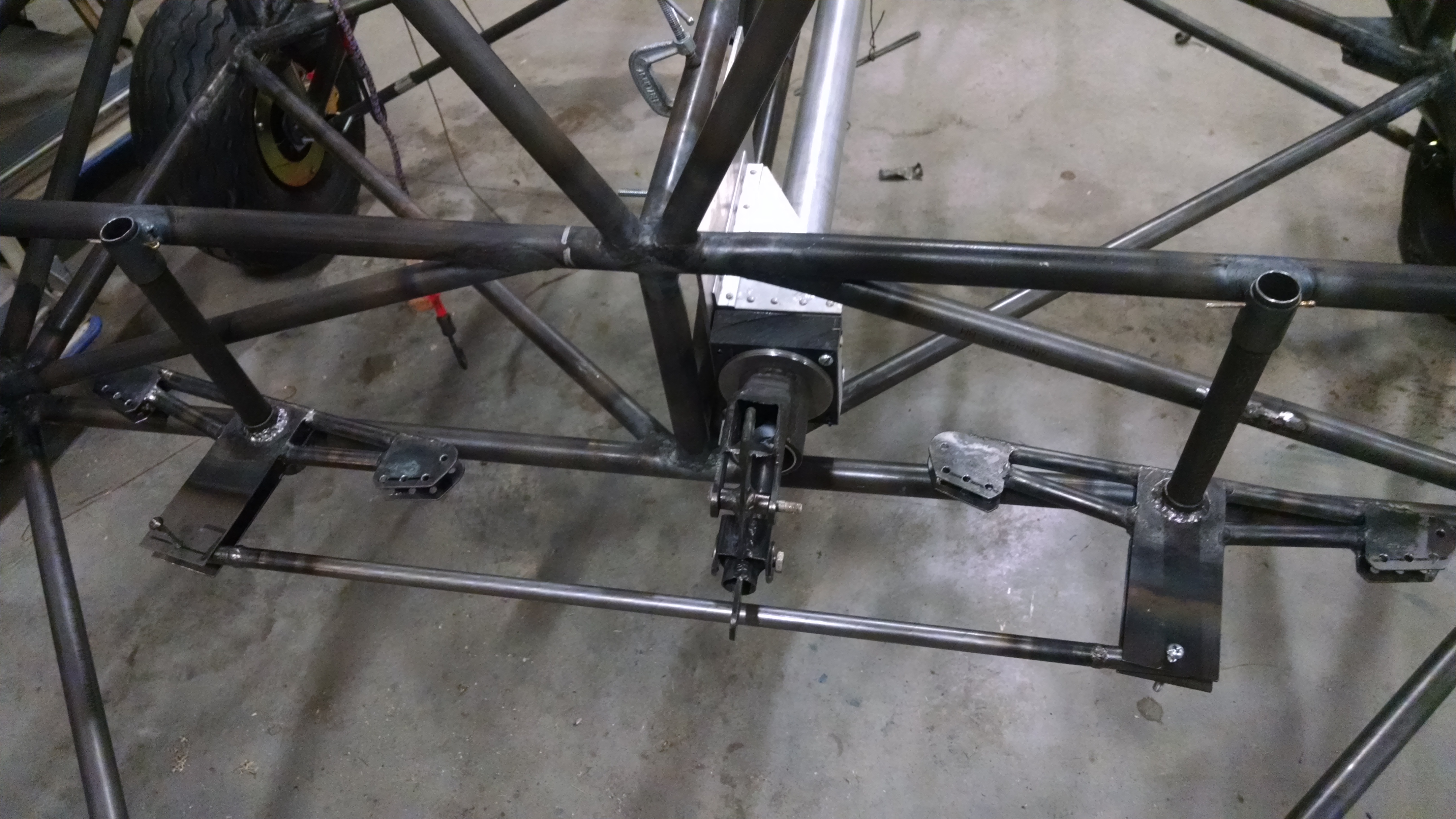 forward about 10 inches to a foot. That puts them just behind the pilot seats and in the cabin where it
 is easy to get to them to make adjustments to the flight control turnbuckles and brake control turnbuckles. This means that the length of the rudder cables which I have already made are now too short. Now I have to make a new set. Since I moved the control six aft now the elevator cables are to long so I will have to adjust them too.
One more change that I have come up with is the cabin doors. The path we we headed down was a fairly traditional one with all of the mechanism of the door mounted within the door. Over the years I have had to work on these mechanisms on several different airplanes. They are a pain in the behind to work on and the mechanisms are prone to failure, especially by the ham fisted. This airplane will get it's share of abuse from people learning how to fly. That has prompted me to revise the concept of placing the mechanism on the outside of the door and attach it to the fuselage structure. This will locate it for easy access and simplify the construction of the door. Of course this is a little further down the road for now.
One more thing I just remembered, I reversed the angle on the tubes just behind the pilots seat. This moved them to the center of the upper cross tube that acts as the auxiliary spar carry through. This was done to better support the loads of a couple of couch potatoes hanging in the sling seats.
So that's pretty much all that I remember of the last 3 months. What's lies ahead is the dual handle brake lever/torque tube design, construction, and installation. I think I have that pretty much figured out. I'll do the throttle system next along with the trim mechanism. Speaking of the trim, I'm going to use a couple of screen door springs to hold pressure on the elevator. I should only need it to hold up pressure because if I rig the airplane to fly correctly no drown trim should be necessary. One thing nice about the trim is that only the pilot in the left seat needs to be able to reach it. That is why I think I will mount it overhead and slightly to the left so that he/she can keep one hand on the control stick while using the other hand to spin the wheel or turn the crank. I'm leaning toward a crank for a couple of reasons that I will address when I get it figured out and installed. After that we will install the doors and the the seats.
December 13, 2015
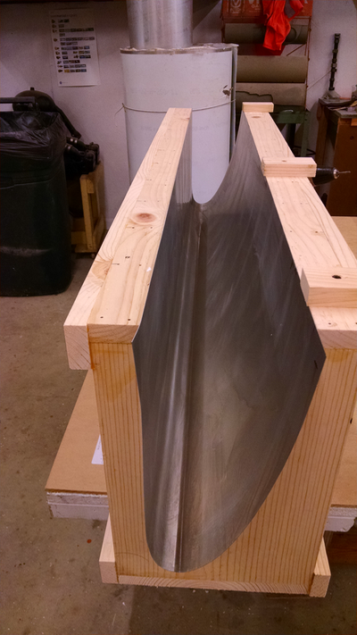
Back at it again. I have just about everything figured out and built except for the wing. I figured that I would start out by building the leading edge. The idea is to hot wire out a length of ribs from polystyrene. I choose to use the extruded kind that you can buy from home depot or some other big store building supply house. People use this stuff as insulation in their houses. The first thing I did was to come up with a way to hold the ribs and then hot wire them out. My idea is to use this same fixture to hold the ribs as they are pressed down into a “saddle,” that holds the leading edge aluminum to shape.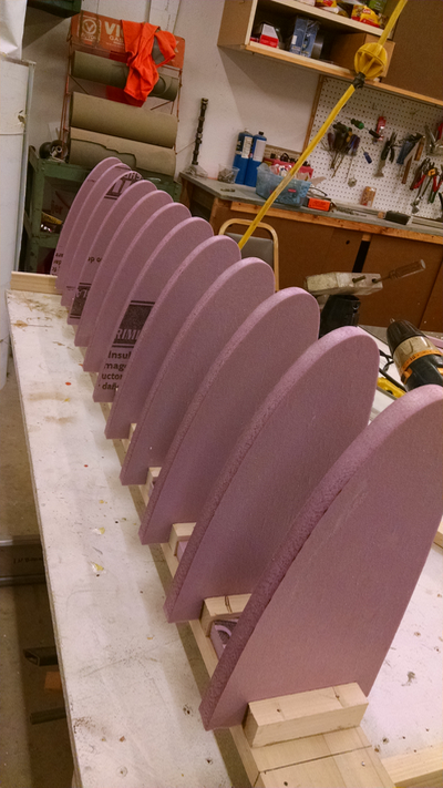
.png)
I though about making a fancy clamping fixture out of aluminum and springs but, I decided that I would make a simple one out of wood. The spacing of the ribs if I recall is 4 inches apart. I made an alignment block to the correct spacing and used it to position small blocks of wood that are glued and nailed to the board. I put a spline on the back to give it stiffness and cut a bunch of squares of foam to jamb between the foam blank and the adjacent rib block. It worked like a charm. Then I cut out a couple of templates to use to hot wire the blanks once they were in place. Matt Curcio had never done any wot wiring before and but he helped me cut out a perfect set on the first try. After the were cut I removed the templates to reinstall later when I make another leading edge piece. The ones that I am making now are only 4 feet long. I think they will be 5 feet long on the next airplane we make.
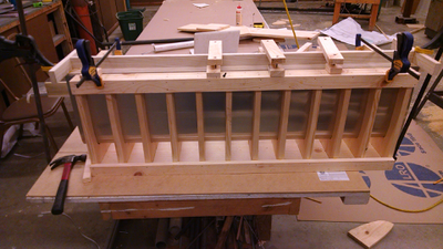
The second thing I did was to make a saddle. My first try was not quite up to the task. All I did was make two end female cut outs and then connect them with a set of rails that supported the edges. The problem was that it allowed the clamping fixture to bow ever so slightly in the middle causing the skin to wrinkle a bit. The next try took some time because I cut out the same number of female saddles as there are ribs, which is twelve in a four foot section. Another problem with so many saddles is not only are they hard to reproduce very accurately, it is just as hard to get them all to line up perfectly during construction of the fixture. I did a pretty good job but it is not perfect. This set up will do for this test wing. The idea is to figure out how to make it and the gluing system is just one of them I do think though that I have it figured out for the production prototype. I will make a box similar to the one I have now except that it will be 5 feet long and I will glue in styrofoam blanks and then hot wire them out with female templates. This will not only make them line up absolutely perfect, the styrofoam saddles will have a bit more give to them when the clamping fixture forces the nose ribs down into the aluminum skin.
By the way I am using .025 bare 6061 T6 for the skin. I might try .020 on the next set, we will have to see what the Dude says about that. He is the one that is doing the stress analysis. Another thing I have to figure out is just exactly how to pre bend the skin before it is forced into the saddle. I tried to do it by guess and by golly and it worked out OK but I think that I can do it better next time by clamping it with a PVC tube and at an exact location. I think it will be pretty easy to get it right next time.
So I have to wait about 24 hours before I can pop it out of the saddle and see how well it all worked out. In the mean time, since I think I have the leading edge process figured out I am going to move on to making all of the clips and the shear web. I will make a drilling template to locate the rivet holes and the machining hole which will be used to hold the aluminum sheet in place in order to route it out with a carbide cutting tool.
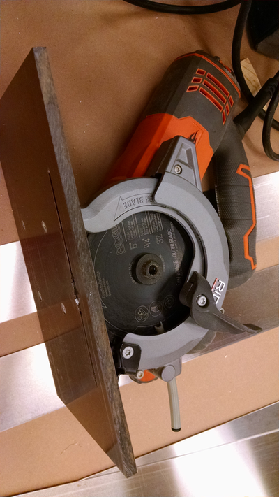
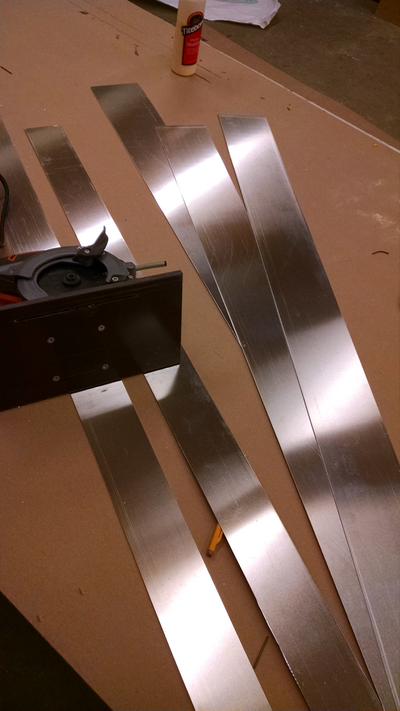
I was also able to put to the test another very important tool needed to make any sheet metal airplane, a saw that cuts very thin aluminum skins. It worked as good as I imagined it might. After a little practice I was able to cut very long cuts as straight as a shear can but, it only cost about $200 to fabricate. I took counter rotating circular saw made by Rigid. Steve made a fixture to mount it to a phenolic guide plate. The saw is only set to about 3/32 inch depth. This allow it to cut just about any thickness of sheet aluminum with deforming the edge. The finished cut needs only the minimum of deburing to make it look perfect. The length of the cut is limited only by the length of the straight edge available. It cut really sweet and the carbide tip blades make short work of the cutting with no rick of kick back.
Ok, here is my long overdue update on the Flaire. It is now April 26, 215 as I write this and I have been doing quite a bit of work on the project but, I have made little headway toward completion. The fact is that I have been making a lot of changes to systems I have already installed. When you design an airplane or any other thing for that matter, you can only visualize so much. It is true that if you use a 3-D drawing program you can take the process forward to a much more precise degree but, you can't figure it all out perfectly in advance.
This is very true of the adjustable rudder pedal system. Where can you go to talk about such a system? You sure as heck can't go to Home Depot and ask an associate. No sir boys and girls, you gotta figure it out on your own. Of course the internet is the source for all answers in the universe. I found a few photos that gave me an idea about what needs to be done to make them work. So I built a set that have the traditional "S" tube in them to route the cable past the pedal in a fashion that will allow them to slip along the cable to and fro while providing a rigid enough fixture to allow the pedals to "grip" the cable once they are set in the desired position.
This is not what I had envisioned in my original design. What I had in mind was a set of small pulleys located at optimal positions on the side of the pedal. But, I built them in the way everybody else does, at least that I could find pictures of on the internet. I figured why reinvent the wheel? Without going into too much detail, after I put the S tube into motion they presented a number of problems. First off, they were difficult to make. Oh sure I could make them, all day long especially if I built some custom rollers. Second, you can't weld them to the pedal, you have to braze them. I had never brazed before and it is not hard to do but there is a learning curve. The biggest problem or issue I encountered with the S tubes was that they did not flex with the cable at the entry and exit ports on the S tube so the cable, which would be stationary in a pedal locked position, would experience sharp bending loads when the rudder was worked. The same was true on the guide tube that directed the cable up along the firewall. And finally cables needed to be clamped in their fixed position with no fitting on them because you couldn't fish the cable through the small diameter S tubes, which by the way had to be lined with nylon tubing to reduce cable chafing at the ingress and egress points. I brazed the ends of these cables and then ground them to a minor taper so they would snake through the S tube in order to make it easy to remove the rudder peal assembly. I insist on this concept of ease of serviceability.
In a nutshell, I wasn't happy with them so I tossed them aside an built another pair like I had envisioned in the first place. It was a couple of days effort of back tracking but they work slicker than cat gut on a brass doorknob! Oh sure the cheap little pulleys work great but they are too heavy. They should be replaced with a set of nylon ones that we can turn out on the lathe. The aluminum side guides make it impossible for the cable to jump the pulleys. I could put a couple of nico thimbles on the end now and nail them directly to the front firewall tubing but I'm going to press on and use the clamps I made for the first set.
So I'm happy with the rudder pedal assemblies which by the way are interchangeable and are held in by only one bolt. Serviceability dude, serviceability. Now for the hand operated differential brake system. I couldn't find any information on these at all on the internet. Toe brakes are a bad idea for students to learn on. I know that is how we do it in this country but it is a really bad idea. I find that a lot of pilots use their toe brakes to control the speed while they are taxing. I have seen several tail draggers flip over on landing because the pilot landed with his/her feet on the brakes and I have seen them stand them on their n
ose too, while they stopped quickly on pavement. When you do this in a nose dragger it covers up for your mistake allowing you to continue poor technique. So we are going to use a hand brake system.The Dehaviland Chipmunk has a great hand differential hand braking system that can be over ridden by the instructor if necessary. The question is how did they do that? Like I said I tried to find some information but couldn't. A friend of mine has one and neither he or his mechanic could explain to me how it works. He said I could take it apart and figure it out but if you ever worked on an English automobile you can imagine what and English airplane would be like. I passed on this and set to trying to figure it out for my own self.
What I came up with took several ties but I think I have it nailed down, we shall see. The simple explanation on how it works is that there will be two brake handles on a torque tube under the seats. There is one handle for the left and one handle for the right seat. Somewhere on this tube will be located a horn or perhaps two of them, that will lead back to the brake cylinders located behind the pilots in the back of the fuselage. So when you pull on the handle it applies pressure to both of the master cylinders evenly. The second part of the equation is a separate cable that leads to the left and right side of one of the rudder synchronizer bell-cranks. You need to have these bell cranks in order to have both the pedals move like the do in all side by side airplanes that have two sets of rudder pedals. It is just a little more complicated if you want to have adjustable pedals.
So what these cables from the bell crank do is shorten the respective cable by however much the rudder is displaced and on the side of the rudder displacement. This happens while the other cable stays the same length therefore holding the same amount of braking as demanded by however hard the handle is pulled back. Got that? If you pull on the handle a little you will get a little braking on both sides but, if you push a pedal while holding that pressure the cable on that pedal is effectively shortened. Walla! Differential hand braking, I think, we shall see.
This system is a little heavier than the simple set in most airplanes, however, they usually don't have adjustable rudder pedals. I know that I can lighten it up a bit by using aluminum bell cranks and horns. A couple of other points are that the assembly will be held in by only one bolt and it will be interchangeable with other aircraft. I built, discarded and rebuilt this assembly four times before I was happy with it. It took me a spell to get it right but I recon it will work I guess.
I changed the position of the control stick too. I originally had the aileron and elevator controls attached to the right side of the center seat support. This caused two things that I eventually couldn't live with. First, the stick was offset to the right by about 3 inches or so from center, which was no big deal. The other thing that was a condition of this simple installation was the stick was probably too far forward. Although it might have been OK, I just couldn't live with it. Simplicity had to give way to function. I ended up cutting the center truss that runs between the two seat almost completely out. The only part I saved was thee center bottom tube. Then I had to use two tubes to allow the center mounted control stick to come up between them. It took a few more tubes than the original idea but it allowed me to mount the stick exactly where I wanted too. I think I moved it back about 6 or 8 inches which removed a small amount of weight. Now the whole system is mounted right in the center like it should be. It's more gooder for sure. A friend of mine has an industrial sewing machine
and was kind enough to make a seat for me. Too bad I'm gonna throw it out too. When I changed the control system it made the cabin a little narrower and now the seat won't fit. It also needed to have one more piece of strapping sewn into it. I have also changed the way tension is put on the seat pan that costs less, weighs less, and is more effective. Again more gooder. What we have is sort of a sling seat that is made out of nylon reinforcing straps and parachute pack material.. I like these seats because they a cheap, easy to make, and most of all they only weigh a few pounds each. Steve Wittman would be proud.I also changed the position of the rudder bell cranks
forward about 10 inches to a foot. That puts them just behind the pilot seats and in the cabin where it is easy to get to them to make adjustments to the flight control turnbuckles and brake control turnbuckles. This means that the length of the rudder cables which I have already made are now too short. Now I have to make a new set. Since I moved the control six aft now the elevator cables are to long so I will have to adjust them too. One more change that I have come up with is the cabin doors. The path we we headed down was a fairly traditional one with all of the mechanism of the door mounted within the door. Over the years I have had to work on these mechanisms on several different airplanes. They are a pain in the behind to work on and the mechanisms are prone to failure, especially by the ham fisted. This airplane will get it's share of abuse from people learning how to fly. That has prompted me to revise the concept of placing the mechanism on the outside of the door and attach it to the fuselage structure. This will locate it for easy access and simplify the construction of the door. Of course this is a little further down the road for now.
One more thing I just remembered, I reversed the angle on the tubes just behind the pilots seat. This moved them to the center of the upper cross tube that acts as the auxiliary spar carry through. This was done to better support the loads of a couple of couch potatoes hanging in the sling seats.
So that's pretty much all that I remember of the last 3 months. What's lies ahead is the dual handle brake lever/torque tube design, construction, and installation. I think I have that pretty much figured out. I'll do the throttle system next along with the trim mechanism. Speaking of the trim, I'm going to use a couple of screen door springs to hold pressure on the elevator. I should only need it to hold up pressure because if I rig the airplane to fly correctly no drown trim should be necessary. One thing nice about the trim is that only the pilot in the left seat needs to be able to reach it. That is why I think I will mount it overhead and slightly to the left so that he/she can keep one hand on the control stick while using the other hand to spin the wheel or turn the crank. I'm leaning toward a crank for a couple of reasons that I will address when I get it figured out and installed. After that we will install the doors and the the seats.
December 13, 2015
Back at it again. I have just about everything figured out and built except for the wing. I figured that I would start out by building the leading edge. The idea is to hot wire out a length of ribs from polystyrene. I choose to use the extruded kind that you can buy from home depot or some other big store building supply house. People use this stuff as insulation in their houses. The first thing I did was to come up with a way to hold the ribs and then hot wire them out. My idea is to use this same fixture to hold the ribs as they are pressed down into a “saddle,” that holds the leading edge aluminum to shape.
I though about making a fancy clamping fixture out of aluminum and springs but, I decided that I would make a simple one out of wood. The spacing of the ribs if I recall is 4 inches apart. I made an alignment block to the correct spacing and used it to position small blocks of wood that are glued and nailed to the board. I put a spline on the back to give it stiffness and cut a bunch of squares of foam to jamb between the foam blank and the adjacent rib block. It worked like a charm. Then I cut out a couple of templates to use to hot wire the blanks once they were in place. Matt Curcio had never done any wot wiring before and but he helped me cut out a perfect set on the first try. After the were cut I removed the templates to reinstall later when I make another leading edge piece. The ones that I am making now are only 4 feet long. I think they will be 5 feet long on the next airplane we make.
The second thing I did was to make a saddle. My first try was not quite up to the task. All I did was make two end female cut outs and then connect them with a set of rails that supported the edges. The problem was that it allowed the clamping fixture to bow ever so slightly in the middle causing the skin to wrinkle a bit. The next try took some time because I cut out the same number of female saddles as there are ribs, which is twelve in a four foot section. Another problem with so many saddles is not only are they hard to reproduce very accurately, it is just as hard to get them all to line up perfectly during construction of the fixture. I did a pretty good job but it is not perfect. This set up will do for this test wing. The idea is to figure out how to make it and the gluing system is just one of them I do think though that I have it figured out for the production prototype. I will make a box similar to the one I have now except that it will be 5 feet long and I will glue in styrofoam blanks and then hot wire them out with female templates. This will not only make them line up absolutely perfect, the styrofoam saddles will have a bit more give to them when the clamping fixture forces the nose ribs down into the aluminum skin.
By the way I am using .025 bare 6061 T6 for the skin. I might try .020 on the next set, we will have to see what the Dude says about that. He is the one that is doing the stress analysis. Another thing I have to figure out is just exactly how to pre bend the skin before it is forced into the saddle. I tried to do it by guess and by golly and it worked out OK but I think that I can do it better next time by clamping it with a PVC tube and at an exact location. I think it will be pretty easy to get it right next time.
So I have to wait about 24 hours before I can pop it out of the saddle and see how well it all worked out. In the mean time, since I think I have the leading edge process figured out I am going to move on to making all of the clips and the shear web. I will make a drilling template to locate the rivet holes and the machining hole which will be used to hold the aluminum sheet in place in order to route it out with a carbide cutting tool.
I was also able to put to the test another very important tool needed to make any sheet metal airplane, a saw that cuts very thin aluminum skins. It worked as good as I imagined it might. After a little practice I was able to cut very long cuts as straight as a shear can but, it only cost about $200 to fabricate. I took counter rotating circular saw made by Rigid. Steve made a fixture to mount it to a phenolic guide plate. The saw is only set to about 3/32 inch depth. This allow it to cut just about any thickness of sheet aluminum with deforming the edge. The finished cut needs only the minimum of deburing to make it look perfect. The length of the cut is limited only by the length of the straight edge available. It cut really sweet and the carbide tip blades make short work of the cutting with no rick of kick back.